Since its commercialization by Sony in 1991, lithium-ion battery technology has seen significant advancements due to its high energy density and efficiency. In 2022, the global inventory of electric vehicles exceeded 26 million units, marking a 60% increase from the previous year. Today, lithium-ion batteries have developed into various forms, ranging from standard 18650 cylindrical cells with capacities of around 3Ah to large pouch or prismatic batteries with capacities exceeding 100Ah. The 4680 battery (46mm in diameter and 80mm in axial length) offers higher energy and power advantages compared to commonly used 18650 or 21700 cylindrical cells. Compared to the 21700 battery, its volume is 5.5 times larger. This large cylindrical battery is expected to reduce the production cost of battery pack assembly due to fewer individual cells required for assembly and interconnection. In addition to Tesla, the manufacturer BMW has also announced a new electric vehicle platform called "Neue Klasse," which uses cylindrical cells with a diameter of 46mm (in two different axial lengths).
Generally, battery manufacturers only provide limited information about the battery characteristics and do not disclose their highly complex and interdependent manufacturing processes. Moreover, battery chemistry and design vary according to the battery and the requirements of the original equipment manufacturers and customers, leading to specific production chains for batteries. In contrast, academic lithium-ion battery (LIB) research often utilizes the characteristics of laboratory scale, small size, or uses small, simple batteries, and semi-manual production processes. Therefore, academic lithium-ion battery research can only serve as a reference for a few performance indicators.
Due to the increasing trend in battery specifications and the instability of available LIB production data, there is growing interest in the scientific community to study the characteristics of large-format cylindrical batteries. The disassembly and characterization of the Tesla 4680 cylindrical battery, which combines a new cell format and a jelly-roll-less architecture, controls the actual battery behavior, thus this study provides a foundation for a better understanding of these characteristics.
This article presents an analysis of the so-called "first-generation" cylindrical 4680 lithium-ion battery extracted from the state-of-the-art Tesla Model Y (2022 model, manufactured in Austin, USA), as follows:
1.In-depth analysis of battery structure and electrode materials
A detailed exploration of the battery structure and a study of the anode and cathode performance are conducted through the use of Scanning Electron Microscopy (SEM) and Energy Dispersive X-ray Spectroscopy (EDX) to analyze material composition.
2.Three-electrode analysis
T-type batteries are assembled to study the anode and cathode characteristics using simulated open-circuit voltage (SOC-OCV) and Electrochemical Impedance Spectroscopy (EIS) under constant current conditions.
3.Thermal imaging analysis during 4680 lithium-ion battery charging
Thermal imaging analysis is utilized to examine the heat generation at the bottom, top, and center of the battery while it is being charged at a 2C charging rate.
4.Electrochemical characterization of multiple batteries
Multiple batteries are characterized for electrochemical performance using constant current charge/discharge and Electrochemical Impedance Spectroscopy (EIS) measurements.
5.Hybrid pulse power characterization of a single cell
The resistive characteristics of a single battery are studied using the Hybrid Pulse Power Characterization (HPPC) measurement method.
6.Open-source provision of all test data
All raw measured data, including battery disassembly images, SEM/EDX recordings, and test procedures, are provided as open-source.

The battery is fully discharged to 2.5V, selected for disassembly, and placed into a glove box specifically designed for the disassembly analysis. Under an atmosphere filled with argon gas, H2O and O2 levels are continuously monitored and adjusted to below 0.1PPM. The specific process is shown in Figures 1 and 2.

Figure 1: Battery disassembly process

Figure 2: 4680 battery disassembly process
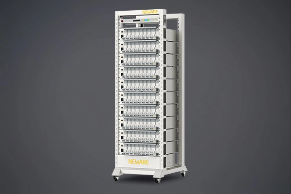
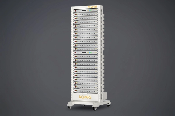
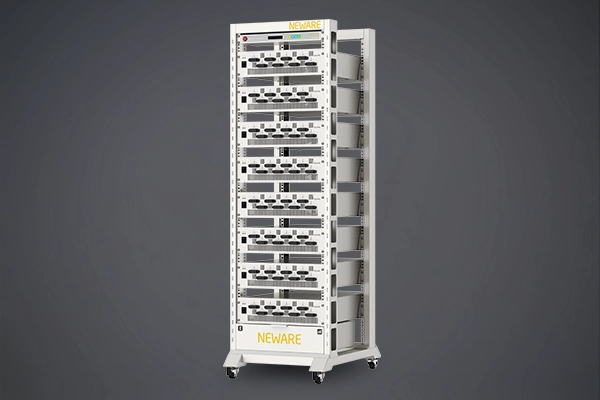
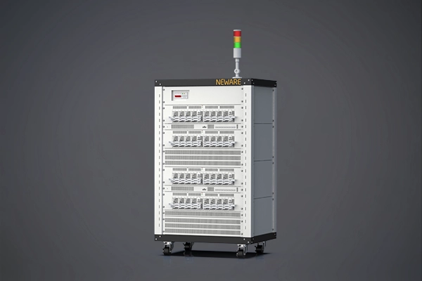
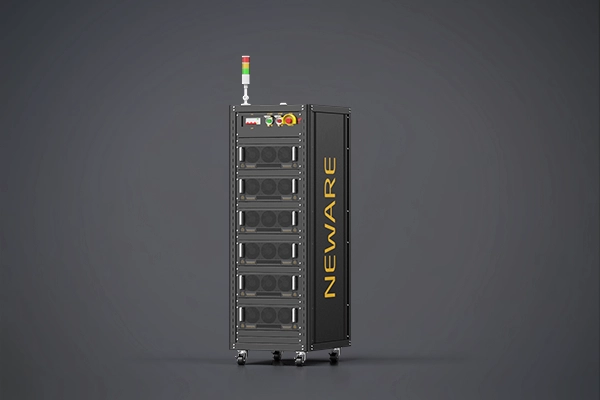
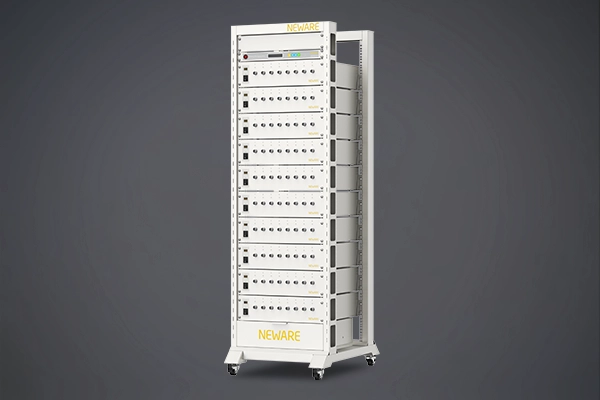
Figures 3 and 4 respectively outline the main equipment for electrochemical performance testing and battery heat generation testing.

Figure 3: overview of electrochemical performance testing equipment

Figure 4: overview of battery heat generation testing equipment

Figure 5: schematic diagram of the 4680 battery components
Figure 5 illustrates the exploded view of the relevant components within the battery. The cylindrical part of the battery has an outer diameter of 46 millimeters and a height of 80 millimeters. The positive terminal has a diameter of 16 millimeters, with an additional 1 millimeter on the basis of the total height of 81 millimeters. A copper rivet is placed at the center of the negative terminal to seal the filling hole. The shell has a thickness of 0.5 millimeters, which leads to a reduction in the internal volume of the cylinder (not considering the seal on the negative electrode side and its three-dimensional form). Compared to commercial batteries such as 18650 or 21700, the increased wall thickness reduces the energy density.
After the removal of the anode and cathode tabs, the jelly roll has a height of 71 millimeters and a diameter of 44.5 millimeters. There is no winding core shaft in the roll core; instead, there is a space with a diameter of 5 millimeters left. The roll is held together at both ends with two pieces of blue tape, each 10 millimeters wide. For the internal connection of the battery terminals, a disc design with notches and folded electrode tabs is used. The cathode tab is made of aluminum, and the anode tab is made of copper, both with a thickness of 0.2 millimeters. The dimensions of the two tabs are shown in Figure 6. Both tabs exhibit hexagonal symmetry but differ in the junction position with the tab connectors. The cathode tab's connector joins at the outer ring, while the anode tab's connector joins towards the center. The anode tab's outer ring is connected to the battery casing, and the center of the cathode tab is ultrasonically welded to the positive terminal of the battery. Thus, when the jelly roll is attached to the casing, the two tabs can function like compensatory elements or springs.
The battery manufacturing process can be reconstructed as follows. Jelly rolls with folded electrode tabs are produced. On the anode side, a copper tab is laser-welded to the copper foil. On the cathode side, the previously ultrasonically welded battery terminal is laser-welded to the aluminum foil. A plastic disk is placed on top of the cathode tab, and then the assembly is inserted into the battery can from the cathode side. On the anode side, a cap with a filling hole is placed on top, and the battery can is crimped and sealed. After the filling process, the filling hole is sealed with a copper rivet. The DataMatrix code at the bottom of the battery cell can contain information. It is assumed to be the unique identifier for this specific battery, used for tracking and tracing applications in the manufacturing process and vehicle deployment. The traceability of the battery is an essential means of ensuring the quality, safety, and efficiency of battery production and use.

Figure 6(a): dimensions of the cathode and (b) anode tabs
The electrode assembly consists of double-sided coated cathodes and anodes, as well as separators, with the lengths and widths of these components shown in Figure 7. Due to the varying widths of the components, they are described in an enlarged form. The structure of the electrodes is similar to that of a conventionally wound battery design, with the anode having a total length of 3403 mm, which is 136 mm longer than the cathode. In the assembled state, the cathode is completely enveloped by the anode.

Figure 7: dimensions of the electrodes and separator of the 4680 battery
In Figure 8, the measured thickness along the electrodes and the calculated areal mass loading is displayed. At both the cathode and anode, the electrode thickness is highest at the core where the winding begins, then decreases significantly. When the electrode length exceeds 1 meter, the thickness increases again. At the same time, the electrode loading, weighed from the electrode samples, remains almost constant throughout its entire length. The unevenness in electrode thickness can be explained as follows: since the battery being opened has already been in operation, the electrodes have undergone volume changes due to the charging and discharging processes. Due to the different compression of the electrodes caused by the varying winding structure of the jelly roll, this leads to subsequent and changing thickness variations.

Figure 8: 4680 battery anode and cathode performance (a) thickness (b) loading (c) density
To conduct a more in-depth analysis of the electrodes, SEM images (Figure 9) were used to study the top and side profiles of the cathode and anode. On the cathode side, spherical active material particles with diameters ranging from 3µm to 16µm were observed, which are characteristic features of typical NMC (Nickel Manganese Cobalt) cathode materials. Elemental distribution was taken from EDX measurements on the surface of the cathode. NMC is used as the active material, and the measurements show it contains 81.8wt% nickel, 12.1wt% cobalt, and 6.1wt% manganese. EDX analysis for fluorine revealed a total amount of 7.9 wt%. It is concluded that polyvinylidene fluoride (PVdF) is used as the binder, as it is one of the most commonly used binders in the cathode. EDX also detected trace amounts (each <0.5wt%) of phosphorus and sulfur, which are residues from the lithium salts used in the electrolyte.
The anode is composed of natural flake graphite. The images show that the particle diameter is 35 micrometers, and EDX analysis confirms that graphite is the only active material, as the presence of silicon was not detected in the measurements. A predominant carbon content of 90.5wt% was detected, which is consistent with the composition of graphite. Additionally, a fluorine content of 7.9wt% was detected, which might suggest the presence of a fluorine-containing binder, such as PVdF or polytetrafluoroethylene (PTFE) found in the cathode. The use of PTFE could indicate a solvent-free anode manufacturing method. Trace amounts of phosphorus and sulfur (each <0.5wt%) were also detected, supporting the hypothesis that they originate from the lithium salts in the electrolyte. Between the coating and the copper collector, a black primer layer can be observed. It exhibits a structure distinctly different from the actual anode coating and extends about 1.5 millimeters beneath the coating. EDX analysis shows that it mainly contains carbon and fluorine, leading to the inference that the same binder used in the coating is employed, with carbon black added for conductivity. This primer layer strongly suggests the use of a solvent-free coating process. The advantage is the elimination of the need for harmful solvents and the avoidance of energy loss during the drying of the electrode sheets.

Figure 9: SEM images observed from different angles
The three-electrode tests indicate that graphite exhibits phase transitions of LiC24, LiC12, and LiC6, respectively, which are characteristic of pure graphite anodes and also confirm the conclusion that the anode does not contain any silicon. The charge-discharge curves reveal that even at a current rate of 0.02C, there is an overpotential of about 0.5 V, indicating a higher internal resistance within the battery. Additionally, the EIS measurement results show that at 50% SOC, the anode has a higher impedance than the cathode, thus the overall battery impedance is primarily determined by the anode.

Figure 10: measurement data of the three-electrode cell
Figure 11(a) shows the measured capacity of the entire battery at different current rates. In a normal battery, an average value of 22.078Ah is obtained at a discharge current rate of C/3, with a standard deviation of σ= 186.2mAh (Table 1). At C/20, in the battery marked as normal, there is an average capacity of 22.411Ah (σ=199.9mAh) during charging, and 22.311Ah (σ=199.7mAh) during discharging. The depicted NOK (No OK) battery exhibits greater variance in all capacity measurements (with a standard deviation of 236.5mAh at C/3, 245.2mAh at C/20 discharge, and 223.1mAh at C/20 charge), but there are no significant anomalies overall.
By calculating the battery data of 083/828, the energy density is determined. Compared to smaller specification cylindrical batteries that have been optimized over the years, the energy density is relatively lower, indicating that the first-generation 4680 battery's conservative design still requires optimization in electrochemical performance, battery architecture, and packaging structure.
Figure 11(b) superimposes the impedance spectra of three batteries (ID 131/828, 186/828, 549/828) at three different SOC levels. The impedance trends of all three studied batteries are highly consistent with the published literature, showing an increase in the main semicircle as SOC decreases, particularly at 20% SOC.

Figure 11: electrochemical performance testing of the battery
The battery (ID 536/828) is charged at a current rate of 0.05C, and the simulated open-circuit voltage curve is shown in Figure 12(a). The battery can be charged with 22.65Ah before reaching the upper cutoff voltage of 4.2V. A constant voltage (CV) stage is not applied. The calculated differential voltage analysis is shown in Figure 12(b), with the corresponding incremental analysis in Figure 12(c). The analysis indicates that the NMC 811 chemistry at the cathode and the pure graphite at the anode contain no silicone. This is consistent with the aforementioned material characterization.

Figure 12: battery simulated open-circuit voltage, differential voltage analysis, and incremental analysis
The results of calculating the battery (ID 186/828) resistance according to Ohm's Law are shown in Figure 13. Similar to other batteries, an SOC (State of Charge) dependency can be observed, which is consistent with the graphite phase transitions shown in Figure 12. A slight dependence of resistance on the current direction is observed, leading to decreased values at higher currents in both charge and discharge directions. This is consistent with previous observations, except for the low SOC area in the discharge direction, which shows an increase in resistance at higher rates. Although previous literature has rarely studied the impact of current rate on battery impedance, this relationship is likely driven by the nonlinear behavior of charge transfer reactions. Previous disassembly analysis of the battery indicates that this effect is particularly pronounced in the low SOC area.

Figure 13: 4680 battery pulse resistance analysis
Figure 14: 4680 battery thermal imaging data
The measurement points extracted from the thermal imaging data are used to evaluate the temperature distribution within the battery can during the charging process, as shown in Figure 14.
 charging")
Figure 15: battery (ID 536/828) heat generation during 1C and 2C CC charging
Figure 15(a) displays the charge and discharge curves of the applied battery. By analyzing the overvoltage, irreversible losses of up to 15W during 2C charging can be calculated, particularly in the low SOC (State of Charge) region. As shown in Figure 15(b), the average surface temperature of the battery (ID 536/828) during 2C charging at an ambient temperature of 25°C is 70°C. This illustrates that cooling large cylindrical batteries remains a formidable challenge under the condition of a lower surface area to volume ratio.
As shown in Figure 15(C), at a charging rate of 2C, the axial temperature difference between TCAP and TBottom is approximately 10K. This could be due to the single-sided electrical contact of the anode and cathode on the lid. Wassiliadis et al. have shown that contact resistance in batteries can generate significant thermal input, especially under high current conditions. Depending on the chosen welding process, these contact resistances might be low in the vehicle, but due to the unilateral contact, they could provide significant thermal input, leading to non-uniform current distribution along the axial direction of the battery.
This study provides a comprehensive characterization of the first-generation Tesla 4680 cylindrical lithium-ion battery (from the Tesla Model Y), addressing the lack of transparency in the development and production of automotive lithium-ion batteries through electrochemical performance and thermal management studies, as well as battery disassembly. The battery is characterized using simulated open-circuit voltage, differential voltage analysis, and incremental analysis. Temperature variations during charging rates up to 2C were investigated for one of the batteries, and disassembly of a battery was conducted, including determination of material composition using SEM and EDX, analysis of battery structure, and evaluation of a three-electrode battery. The main findings from each area can be summarized as follows.
The hexagonally symmetric anode and cathode tabs, designed without protrusions, serve as compensatory elements or springs when connecting the roll core to the casing. Compared to traditional cylindrical batteries whose casings are not used as structural components, the casing has a higher thickness. The electrode winding consists of double-sided coated cathodes and anodes with two separators, and there is no core shaft within the battery cell. The electrode loading remains almost constant along the electrode, but the thickness of the electrodes varies. Spherical active material particles are found on the cathode side, while the anode is composed of flake graphite particles. EDX confirms that graphite is the sole anode active material, with no detected presence of silicon. The use of PTFE suggests a solvent-free anode manufacturing method, especially evident from the primer between the coating and the copper collector coating. Three-electrode analysis reveals the battery's electrochemical specific potentials and the whole-cell impedance dominated by the anode.
Using data from a single battery, the calculated energy densities were 622.4Wh/L and 232.5Wh/kg, indicating a conservative design for the first-generation 4680 battery. Simulated open-circuit voltage analysis (differential voltage analysis and incremental analysis) confirmed the NMC 811 chemistry and the pure graphite anode. HPPC measurements revealed a characteristic SOC (State of Charge) dependency with increased resistance in the low and medium SOC regions. During 2C charging, relatively high surface temperatures were observed in a free convection setup—highlighting the need for adequate cooling systems within battery pack components
Some materials in this article are sourced from the internet. If you believe there is an infringement, please contact us.
NEWARE TECHNOLOGY LLC
755 Ames Avenue, Milpitas, CA, USA, 95035